


2026-01-15
A device for visualizing corona discharge of biological objects based on the Kirlian effect

The Kirlian effect is a physical phenomenon associated with the occurrence of a corona discharge in a gaseous medium around an object located in a strong, non-uniform electric field [1]. When high voltage is applied to an electrode separated from the object by a dielectric layer, air ionization occurs, accompanied by a characteristic glow. Recording this glow allows for a visual image of the electric field distribution and discharge processes, which forms the basis of so-called Kirlian visualization.
Interest in the Kirlian effect stems from both its visual appeal and its wide range of possible applications. It is used in educational demonstrations in high-voltage physics, in the study of corona discharge and gas discharge processes, as well as in experimental and applied setups for analyzing the properties of materials, biological objects, and surface effects. Despite the existence of commercial and laboratory solutions, developing our own device allows for a deeper understanding of the physical principles of the phenomenon and optimizes the design for specific applications.
The purpose of this work is to develop and describe a device for visualizing corona discharge based on the Kirlian effect. This article discusses the physical foundations of the effect, the design principles of the high-voltage portion of the device, insulation and safety requirements, and methods for obtaining and recording discharge images. Particular attention is given to the practical aspects of device implementation and an analysis of factors affecting the quality and reproducibility of visualization.
Device Circuitry
The schematic diagram of this device is shown in the following figure. Line voltage is applied to input contacts X1–X2, which is reduced to 15 VDC using AC-DC converter U1. The resulting voltage is used to power the output stage, implemented on transistor Q1, as well as the linear regulator U2, which further reduces it to 12 V.
 Fig. 1. Schematic diagram of a Kirlian corona discharge device. |
A stabilized 12 V voltage supplies power to signal generator U3, which is based on the widely used NE555 microcircuit. The generator generates a pulsed signal with a frequency of approximately 7.5 kHz and a duty cycle of approximately 10–11%. The duty cycle is adjusted by resistor R2.
The generator's output signal is fed to the control input of switching element Q1, which switches the primary winding of high-voltage transformer THV1. The transformer (XHV1) outputs high-voltage pulses, which are then applied to the device's conductive glass to generate a corona discharge.
The THV1 transformer operates in a mode atypical for similar devices—as a quarter-wave Tesla transformer with one end grounded [2]. Grounding is achieved through the electrical network using high-voltage capacitors C1 and C2. For this reason, the circuit uses a built-in power supply (U1) rather than an external adapter. To ensure free oscillation, the transformer's primary winding does not have a free-wheeling (damping) diode.
Inductor L1 is connected in series with the primary winding of the THV1 transformer. It is designed to limit the current consumption in idle mode, when the biological object is not in contact with the device's surface. In extreme cases, inductor L1 can be eliminated from the circuit; however, this increases the thermal load on the transformer and output transistor.
Component Base
AC-DC converter U1 converts AC mains voltage to 15 V DC and must provide an output power of at least 12 W. Any power supply model that meets the specified requirements can be used to implement this function. Proven solutions include the Mean Well NFM-15-15 [2] or EPS-15-15 [3] series converters, which are characterized by high reliability and stable output parameters.
The THV1 high-voltage transformer must have at least five secondary winding sections and be built on a ferrite core. It should be noted that Chinese manufacturers often do not provide the exact names of the radio components.Comrade. In online retail stores, particularly on Aliexpress, this transformer is usually labeled as "20KV High Frequency High Voltage Transformer Ignition Coil". Its appearance is shown in Figures 2 and 3, and its location on the printed circuit board is shown in Figure 4.
| Fig.2. Appearance of THV1 | Fig.3. THV1 Appearance |  Fig. 4. Layout of components on a printed circuit board |
Inductor L1 contains three turns of thick copper wire wound on a ring-shaped core made of nanocrystalline material with dimensions 10×14×4.5 mm. Please note that increasing the conductor diameter reduces the inductor's heat dissipation. It is recommended to use a wire with a diameter of at least 1 mm, preferably Litz wire of equivalent cross-section. Any other inductor with similar parameters can be used: a current of at least 5 A and an inductance of approximately 80 µH.
List of other circuit components:
- U2 - 12-volt linear voltage regulator LM7812, in a TO-220 package;
- U3 - pulse generator NE555 in a DIP package;
- Q1 - MOSFET transistor IRF3205 in a TO-220 package. It needs to be mounted on a small radiator;
- D1, D2 - diodes 1N4148;
- D3 - diode UF4007;
- C1, C2, C7 - high-voltage ceramic capacitors: 4.7 nF * 6.3 kV;
- C3, C5 - ceramic capacitors for any voltage;
- C4 - film capacitor: 2.7 nF (any voltage);
- C6 - film capacitor: 470 nF * 100 V;
Resistors of any type with a rated power of 0.125–0.25 W can be used.
One more design element needs to be mentioned: the two panes of glass installed between the panels. Each pane is coated on one side with indium tin oxide, allowing it to conduct electricity while remaining transparent. The glass dimensions are 50x50x1.1 mm. On Aliexpress, it's called "Transparent Glass Indium Tin Oxide ITO".
Printed Circuit Board
The PCB design took into account the placement of power and high-voltage circuits, as well as electrical insulation requirements.
The board has a mounting location for one of two AC-DC converters, U1: Mean Well NFM-15-15 or EPS-15-15. The NFM-15-15 is preferred.
Production version: PCB (open)
The production option provides a set of documentation for manufacturing a printed circuit board in production:
GERBER file for PCB, BOM file of the specification of components and a schematic diagram showing the values of the elements.
All this allows you to immediately order a PCB, for example, here, and then quickly assemble it.
 |
One corner of the PCB has a "TRIM" line, which allows for mechanical trimming of the board corner. This ensures that the high-voltage terminal XHV1 is insulated in air, which in some cases provides better electrical insulation than fiberglass.
Assembling the Device
The most difficult stage of device assembly is installing the two glass plates and connecting them to the electrical circuit. The glass plates are installed in the groove of the first panel sequentially: first the first glass plate, then the copper busbar, and then the second glass plate. The conductive surfaces of the glass plates should be oriented inward and in contact with the copper busbar (Figs. 5–6). The conductive side is determined using an ohmmeter by measuring the resistance between the probes. To secure the glass plates, a small amount of cyanoacrylate glue (superglue) can be used, allowing it to set for at least 30 minutes until it fully sets.
The copper busbar is an L-shaped strip cut from a thin copper sheet. An insulated wire is soldered to the busbar and routed through a service hole (Fig. 6). This wire is then connected to the high-voltage terminal XHV1 of the THV1 transformer.
 Fig.5. Two panels for glass mounting |  Fig.6. Assembling the glass on the first panel | 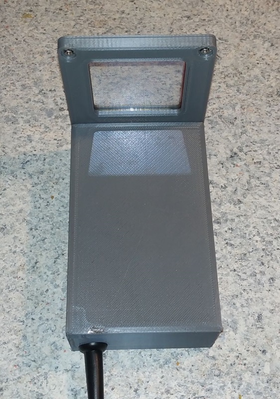 Fig.7. Assembled device |  Fig.8. Kirlian glow around the finger |
The assembled unit is secured with a second panel and tightened with two M2×6 screws through the upper mounting holes (Fig. 6). The lower screws are installed after soldering the wire to the THV1 transformer, after which the panels are finally secured to the housing with M2×10 screws (Fig. 7). A larger diameter lower screw (M2.5–M3) may be used. This design ensures mechanical strength, electrical isolation of the user from high-voltage circuits, and reduced charge leakage between the transformer and the conductive glass.
Production version: 3D body (open)


The 3D model of the device consists of four separate parts: the housing, the cover, and two glass panels. Each part is represented as a separate file and can be manufactured either together or separately.
Circuit Setup
If the precise output voltage of AC-DC converter U1 is not known, it is recommended to perform the initial setup without the high-voltage transformer THV1 installed on the board. The output voltage of U1 should be set in the range of 14.5–15 V. Additionally, it is recommended to monitor the waveform on the gate of transistor Q1 using an oscilloscope. The pulse repetition rate should be approximately 7.5 kHz, and the duty cycle should be approximately 10%. After checking these parameters, the transformer THV1 can be installed and soldered.
Before turning on the device for the first time, trimmer resistor R2 should be turned to the far right position (clockwise). After turning on the device, hold any conductive object, electrically insulated from the user, near the glass surface. By smoothly rotating resistor R2 counterclockwise, set the desired corona discharge intensity. Typically, the regulator's operating position is near the midpoint of its full travel.
Caution. When working with the device with the cover open, strictly observe electrical safety precautions. Converter U1 is live.